Soil Mechanical Properties Testing
The quantitative accuracy of DEM soil simulations useful for engineering design and prediction depend on how well DEM micro-scale particle interactions produce bulk mechanical behaviors that replicate those of real-world physical soils. Bulk soil mechanical behaviors (geotechnical properties) include the stresses, deformations, and volume changes that occur under the influence of externally applied loads or displacements.
Sometimes, it is sufficient to know only the peak stresses that occur, which is traditionally defined as the soil strength. For many problems the complete soil stress, deformation, volume change information is needed to provide accurate solutions.
Two examples of this are the Mars Exploration Rover wheel mobility and asteroid extraction forces problems. Soil geotechnical properties are commonly measured using the triaxial shear, the direct shear, and the tensile strength laboratory tests. In-situ soil mechanical properties are often estimated using penetrometer force as a function of penetration depth measurements or other in situ tests. DEM simulations of physical geotechnical tests are used to determine the micro-scale DEM parameters that produce the best match of DEM and physical soil bulk mechanical behavior.
Once an optimal match between DEM and physical soil bulk behavior is found, simulations of engineering problems can be validated using available data and to predict mechanical behavior in conditions were data is not available. This is possible because DEM simulations produce emergent solutions over the whole range of conditions where the DEM particle micro-interaction rules are representative of physical processes.
Information about geotechnical properties testing and their use in calibrating DEM simulation parameters can be found in:
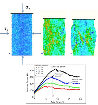
1) Triaxial shear test apparatus showing three stages of DEM soil deformation at constant displacement or strain rate in the upper panel. A confinement stress, σ3, is imposed on the soil through a flexible membrane and an axial stress, σ1, (the deviator stress) is applied through a vertical loading ram via incremental increases in stress until failure or via a constant deformation rate. Stress versus strain for triaxial shear tests at four different confining stresses are shown in the lower panel. Volume change information (not shown) can also be determined from the DEM simulations.
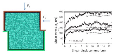
2) Direct shear test apparatus with normal force (FN) and shear force (Fs) shown in the left image. The shear force may be applied incrementally or through a constant displacement rate. Shear stress versus shear displacement for cohesive DEM particles are shown in the right hand image for particles with surface energy of 40 J/m2. Normal and shear stresses are calculated from the area of the DEM particles in contact between the upper and lower shear box containers.
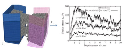
3) Tension strength test apparatus showing a test in progress for cohesive DEM particles (left image). The tension force (Ft) is increased incrementally or through a constant displacement rate pull. Simulation test results for DEM particles with three different particle surface energies.
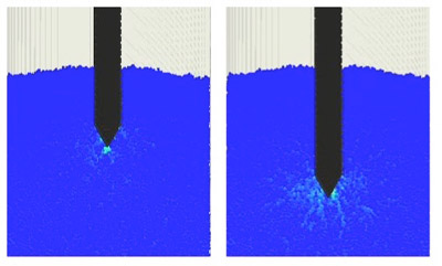
4) A soil cone penetrometer test at two different penetration depths showing the force chains (light blue) emanating from the surface of the penetrometer tip. Penetrometer (and other in situ method) test data are often calibrated to triaxial or direct shear data to interpret penetrometer measurements.
Kulchitsky, A. et al. 2016. Resistance forces during boulder extraction from an asteroid, Acta Astronautica, 127:424-437
Johnson, J. et al. 2015. Discrete element method simulations of Mars Exploration Rover wheel performance, J Terramechanics, 62, 31-40, (2015)
Knuth, M. A., et al. (2012). “Discrete element modeling of a Mars Exploration Rover wheel in granular material.” Journal of Terramechanics 49: 27-36.
Das, B. M. (1998). Principles of geotechnical engineering. 4th edition, Boston, PWS Publishing Co., 712 pp.